The idea behind this project is to create a series of 3D paths (polygons) representing the trunk and branches of a tree or a similar asset, and then to apply a user-defined instanced mesh to each of the paths' segments.
The tool also allows to create custom geometry on the fly from SVG-like strings and load GLTF models.
Every asset can be saved locally either in an internal text format for re-import and further editing or exported as a stand-alone HTML page.
The code is written in vanilla JS and only requires THREE.js library.
SPDX-License-Identifier: MIT
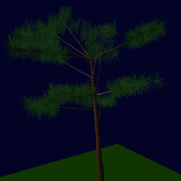
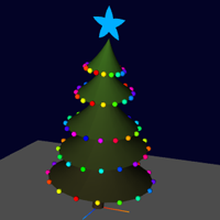
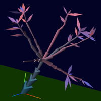
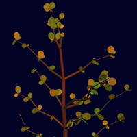
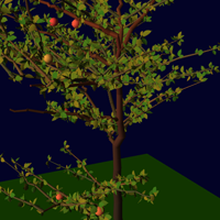
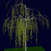
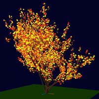
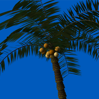
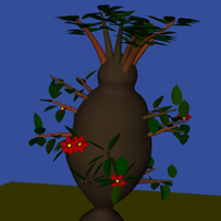
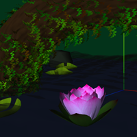
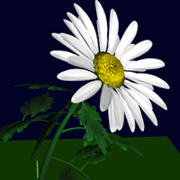
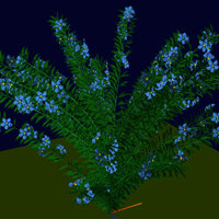
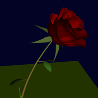
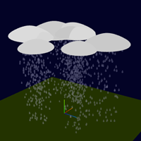
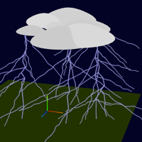
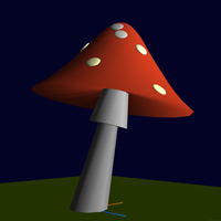
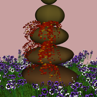
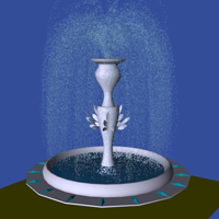
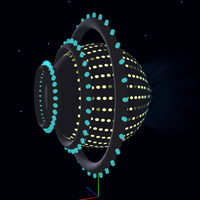
While there are more ready-to-use examples provided with the tool, below is the general overview of what can be done. Click on the image to load the asset. Refer to section for more details.


To load an existing asset choose a group and a name from import panel on the right and press button.
To randomly re-roll a part of an asset use buttons and to re-build the instanced mesh.
To save your project use the left bottom panel; choose the desired format and press and buttons.
To start your own asset from scratch use to load the default settings and the desired number of branch levels.
Every asset is made out of paths (polygons) and an instanced mesh that is then assigned to each segment of the path. Level 0 branch paths are attached to the vertices of the trunk polygon, the branches of level 1 - to the level 0 and so on. The maximum level of branches is set to 8 and can be further increased using cap_level GET variable.
Each path is created inside a volume of height length and width w. Smaller values of w make paths more straight, bigger - more zig-zagged.
The minimum allowed distance between vertices is min. At first, a num number of vertices is randomly generated and then vertices that are too close to each other are discarded. Thus, the maximum number of segments on a path is length / min and can be seen in the statistics ( button at the right bottom panel). The actual number of vertices will vary every time the path is generated. For example, if min > length the polygon will have one segment.
Bigger values of num generate paths with shorter and more evenly distributed segments length-wise, smaller - create less segments with a higher length variance.
For the trunk only, x and z biases tilt the path from it's original vertical direction (along Y axis).
Branches of the current level are randomly attached to the vertices of the previous one. When positive, seg.off is the number of segments from the beginning and the end of the parent path that are excluded from such attachment and will not hold any child branches; when negative - only some segments from the beginning and the end of the parent path are allowed. For example: [0, -1] allows the first and the last segment, [1, -1] - only the top, [-0, 1] - only the bottom. This setting affects the next level of branches which needs to be re-generated to see the change, re-generation of the current level is not required.
The total number of branches is tot, while y-bias represents the range of angles between the branches and their parent. The angle will be randomly chosen between the two numbers provided, it can be set from 0° to 180°, where smaller values make branches lean forward.
By default, paths branch off of the parent in all directions (in the cross-section). Sometimes it's necessary to branch off mainly in one or two directions, for instance, to the left and to the right of the parent path. Setting fi contains four angles; about half of child paths will branch off in between the first two angles and the other half - in between the last two. So, to create "left-right" branching one could use '-30,30, 150,210'. The checkbox rel.fi allows further control by accounting for the rotation of the parent branch, while follow helps flat shapes like leaves to face the direction of the parent. Change rel.fi and follow for "branch level 0" in this example to see their effect: .
Gravity angle grav will bend up or down every segment of every branch subsequently by a specified angle after their final placement. Use this to create curved paths. This transformation requires a fair amount of calculations.
The color of each level of paths is set randomly to help to tell them apart while editing an asset. If some paths are exported with the asset, their specific color can be set as three (rgb) or four (rgba) CSV numbers in the range of [0, 1].
To attach a path to the last vertex of the trunk, instead of a random parent path vertex, set tip checkbox.
The interface exposes the code used to create the geometry and the material of the instanced mesh via mesh object that has the following parameters:
height - to scale mesh instances so they match path segment lengths, the height of the geometry (mesh.geo) needs to be known. For built-in THREE geometries like Cylinder or Sphere, it will be figured out automatically from their constructor. In case of custom geometries, height needs to be provided explicitly.
attenuation - mesh instances are scaled down (attenuated) in their cross-section (XZ) as they progress down the path, from segment to segment. The value ranges from 0 to 1, the default being 0.66.
uniscale - if set, additionally scales mesh instances in their cross-section (XZ), on top of attenuation, to preserve, if possible, the mesh shape along all axes, for example in case of a sphere.
shineThrough - creates an illusion of a mesh being translucent, like a tree leaf, controls the amount of light that passes through and radiates from the back side, value from 0 to 1, default 0.5.
For a better match between segments, the geometry can be slightly scaled or translated along Y-axis. All THREE scale, rotation and translation transformations can be applied to the geometry, as ususal, along with some custom functions:
twist & profile - currently work only on Cylinder and Sphere geometries; will rotate around Y axis and scale in the XZ cross-section respectively the vertices of the geometry and recalculating normals, these functions are uv seams aware.
noisePos & noiseNor - currently work for Cylinder, Sphere, Torus and Lathe geometries; will add noise to positions and normals respectively to add more variations to the surface. The normals will mismatch the vertex data after the call.
Custom LeafGeom constructor accepts either a name of a leaf provided with the tool or a src property containing a FXG string to create a leaf shape on the fly (currently supports quadratic Bezier curves and lines). Add elog(leaf.src); to the code after the leaf constructor to print the source for the current leaf to the bottom left panel; makeZ property of the constructor object is a function that generates z-component for each vertex of, otherwise flat, shape. The function accepts x and y coordinates of a vertex as parameters. The quality parameter defines how closely shape polygons will follow Bezier curves (default value is 0.33). Smaller values result in higher vertex count. In case of a low-poly shape that needs to be curved significantly via makeZ and doesn't have enough geometry in the middle to express the curvature, bisecDist can be used to split existing triangles into smaller ones. The value is the maximum allowed triangle side length as a fraction of the shape's bounding box diagonal, see for an example.
Constructor PetalGeom works the same way except the supplied name will refer to a different shape. For example, there is petal "daisy" and leaf "daisy".
Applying textures can be done via THREE texture loader texldr, use maybeRender as the onLoad callback function, see this example .
Color array is used to give each segment mesh a different color, if needed, must be always set and will be mixed with mesh.mat.color, if present.
Instanced mesh with petals object defined has an extra functionality. The mesh vertices will serve as attachment points for the secondary "petal" mesh. This allows to create regularly positioned meshes as opposed to the random appearance of all others. The arrangement of petals on the geometry of the main mesh will be repeated on all instances.
Apart from the material and the geometry, the properties include ybias that works in the same way as for the path config, the angle is relative to the current branch segment direction. If usenormals is set, the angle will be instead counted from the normal of the vertex to which the petal is attached. To use only a subset of the main mesh vertices for attachment, set offset property (from the beginning and the end of the vertices list). The third number in offset array, if present, represents the percentage of vertices that will be (randomly) chosen for attachment. Vertices lying on the Y axis of the mesh are excluded by default, set usecenter to include them as well.
Petals can be assigned colors via petals.color. If this array is shorter than the total number of petals on all instances of the main mesh, the colors will start to loop over. The array must be at least as long as the number of petals on one instance.
'mesh' and 'petals' should be treated as reserved words and can not appear anywhere else in the code, including strings, URLs etc.
After changing any "path config" values (except seg.off) press button to see the result. All child levels below should be automatically re-adjusted to match the new path. To see changes made to seg.off re-generate the level below.
Press to see changes made to the instanced mesh code.
On the tool page, render path and render meshes settings only change their respective visibility (they will be generated anyway). When exporting as a stand-alone HTML, these settings define if respective paths and instanced meshes will be created.
All the data from a particular level can be copied using button to the right of the title. Pressing on another level will replace its data with the copied one. After pasting new data to the child level, it needs to be generated and updated before its parent, to avoid errors.
Each level can have a script added to the main animation loop, use link to switch between editing of instanced mesh and animation scripts. If a layer has an animation attached to it, the link will be highlighted.
The code will be executed on each frame, the global object G is available for storing any persistent values in between frames and also for initialization, along with: imesh & petals - shortcut for instanced meshes of the current level, frame - current frame. The following functions are available as well:
getBloomDirs - returns an array of quaternion direction vectors for each petal that will rotate petals in a way that will make the flower open or close. Use this together with quaternFromETh to create an actual quaternion.
getImesh - returns scale, position and rotation for each instance from an internal storage; getPetal - same as getImesh, also returns the normal vector to which the petal is attached and the direction of its parent path segment.
setImesh & setPetal - set position rotation scale and color for an instance with the specified index via setMatrixAt & setColorAt. Properties prefixed with underscore (like '_x') will be set directly, properties without - will be added to the storage values first, before setting.
All these functions get extra parameters added on the fly via regexp, so their arguments can not contain round brackets.
The whole tree data and 3D structure can be accessed via this - use log(this); to print it in the console.
Use to apply changes made to the animation code, to control the playback of the animation of the current level and to clear G object and reset the instance/petal meshes. Use the same buttons on the top left canvas overlay to control all levels at once.
An internal tree data format can be used to save a project to a file for importing and editing it later. An asset can also be exported as a stand-alone HTML file.
RNG state will preserve the exact look and feel of the asset, otherwise, after importing, an asset will be generated based on the same path and instanced mesh settings but with different random numbers. Check camera controls if you want the code to be added to the generated HTML file.
calculates the maximum path segments value (length / min) for each level, to compare against num, as well as the info about the actual size of instanced mesh arrays.
To import a preset provided with the tool, choose a group and a name on the left of the import panel and press .
To import a local data file from your computer, either drag and drop the file on the text input element on the right of the panel or click and choose a file. To load an external file (in tree format), type in the URL and press . Due to CORS policy, the external file will only load if CORS header is set in the server response.
To add a gltf file for use with a new asset, click the link next to import panel title to open "GLTF import settings" pop-up window. Type in names and file URLs in the JS object format and press . If the loading is successful, each file content will be available in the instance mesh setup as 'GLTF.objectName', where 'objectName' is the name provided in the import settings, see for an example.
The object provided in "GLTF import settings" will be exported along with other data and gltf files will be loaded automatically next time the file is opened.
Some of the settings are added to the page's URL in GET format and require (re)loading it.
Currently supported variable names: default - don't load any presets; mav_lev - number of branch levels, group - asset group, name - asset name.
Examples:
- new asset with 5 branch levels,
- load a specific asset
Press , change the number of levels in the text, for example, max_lev:4 to the desired one, press and reload the asset, it should now be loaded with the new number of levels and will be saved accordingly.
If the number of levels is reduced, some additional manual cleanup might be required in the seeds section of the data file.